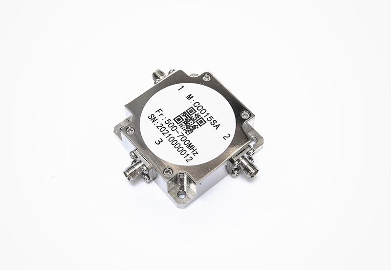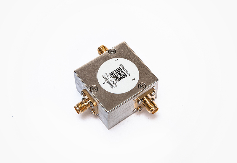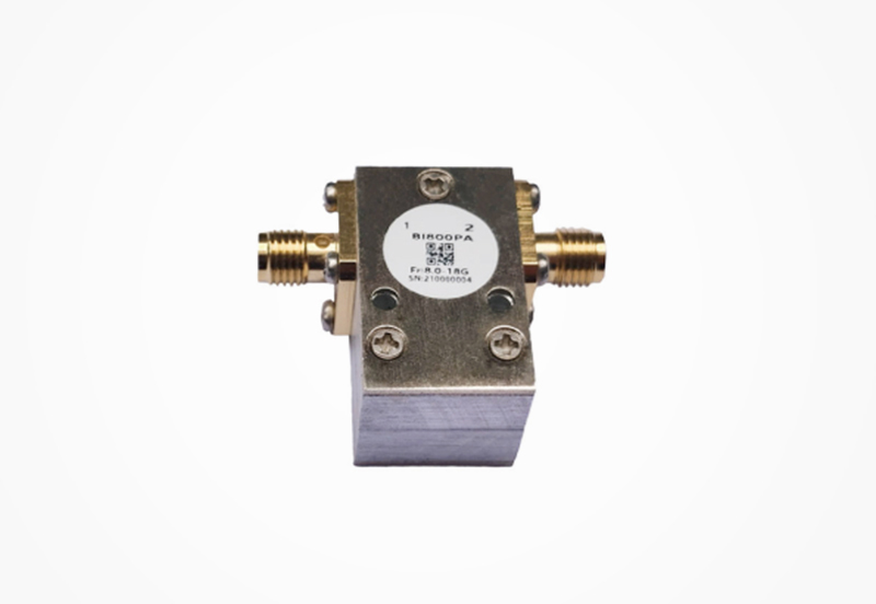




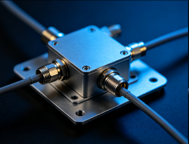
RF circulators integrated with SMA female connectors are essential passive microwave components widely deployed in modern wireless communication, radar, and RF testing systems, serving as directional signal control devices with unidirectional transmission characteristics. Unlike male connector variants, SMA female circulators feature threaded female port interfaces that deliver superior mechanical compatibility and connection stability in complex engineering environments. The standard SMA interface supports a broad frequency spectrum ranging from 0.698 GHz to 18 GHz, covering common UHF, SHF, and microwave frequency bands, which enables these circulators to adapt to diverse civilian and industrial RF equipment configurations. Most commercial models adopt a three-port coaxial structure, maintaining the core circulator function of transmitting signals sequentially from port 1 to port 2, port 2 to port 3, and blocking reverse signal transmission to ensure signal isolation and anti-interference performance.
The structural design of SMA female connectors endows the circulator with distinct practical advantages in system integration. The threaded locking mechanism of SMA female interfaces effectively prevents loose connections caused by vibration, mechanical impact, or long-term operational fatigue, which is critical for outdoor base stations, vehicle-mounted radar systems, and mobile RF testing devices. In addition, female connector ports avoid the pin damage risks associated with male connectors during frequent plugging and unplugging, extending the overall service life of the circulator. High-quality SMA female circulators are manufactured with precision-machined copper alloy connectors and gold-plated contact surfaces, reducing contact resistance and signal attenuation while enhancing corrosion resistance in humid and dusty working conditions.
Electrical performance parameters further define the application value of SMA female connector circulators. Premium products achieve an isolation level above 40 dB within the operating frequency band, effectively isolating reflected signals and cross-port interference, while the insertion loss is controlled below 0.3 dB to minimize valid signal power loss. Power handling capabilities vary by model, ranging from 5W low-power versions for laboratory testing to 300W high-power variants for industrial communication systems. These circulators are widely applied in antenna transceiving systems, RF amplifier protection circuits, and signal duplexing modules, providing reliable directional transmission and isolation guarantees for compact, high-stability RF system designs.
Impedance matching is a core technical requirement for integrating RF circulators into 75-ohm communication systems, as conventional microwave circulators are typically designed for standard 50-ohm impedance systems, leading to severe signal reflection, power attenuation, and system mismatch if directly applied to 75-ohm equipment. 75-ohm impedance systems are predominantly used in cable television broadcasting, satellite television transmission, and high-definition video RF signal distribution systems, which differ from 50-ohm systems optimized for wireless communication and radar devices. A dedicated 75-ohm matched circulator is engineered to eliminate impedance discontinuity between the circulator core and 75-ohm transmission lines, ensuring maximum power transfer and minimal signal reflection in the entire signal transmission chain.
The impedance matching design of 75-ohm circulators relies on precise optimization of the ferrite core structure, internal transmission line dimensions, and port impedance conversion circuits. Designers adjust the thickness and diameter of the ferrite resonator, optimize the length and width of the microstrip transmission lines inside the circulator, and integrate low-loss impedance matching networks to calibrate the port impedance accurately to 75 ohms across the full operating frequency band. Unlike universal 50-ohm circulators, 75-ohm matched models strictly control the voltage standing wave ratio (VSWR), with a typical VSWR value lower than 1.2:1 in the working frequency range. This low VSWR characteristic ensures that almost no signal energy is reflected at the connection interface, avoiding signal distortion and power loss that would degrade the stability of video and broadcast signal transmission.
The practical application value of 75-ohm impedance-matched circulators is prominent in wired RF transmission systems. In cable TV head-end equipment, these circulators isolate reverse signal interference generated by user terminal equipment, preventing signal backflow from disrupting the main transmission network. In satellite TV receiving systems, they protect low-noise down-converters from reflected signal damage while maintaining stable unidirectional signal transmission. Moreover, the optimized matching structure ensures consistent electrical performance under varying temperature and power load conditions, enhancing the environmental adaptability of the system. By achieving seamless impedance matching with 75-ohm coaxial cables and terminal devices, these specialized circulators fill the technical gap of directional signal control in broadcast-grade RF systems.


Contact Phone:
0755-26701085 0755-26701002
Company Address :2nd Floor, Building A, Juchuang Jingu Creative Park, Xili Street, Nanshan District, Shenzhen