







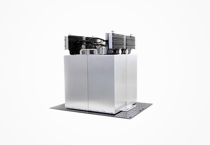
Frequency combiner is widely used in general communication network relay stations as well as various specialized and public mobile communication networks. This device can combine 2 to 16 base station transmitters into a single transmitting antenna, which not only saves the engineering costs of antennas, feeders, and tower setup but more importantly, this product uses high Q value cavities, ring isolators, and other components to effectively suppress the out-of-band noise and high-order harmonics of transmitters, improving the purity of the transmitted spectrum and fundamentally solving the intermodulation interference problems that are difficult to address in multi-antenna installation scenarios.
The device supports various customized frequencies and features low temperature drift, low insertion loss, low intermodulation, and high isolation.
Product Advantages:
Main frequency bands: 136–174MHz / 330–520MHz / 851–869MHz
Temperature and power drift: <20kHz
Insertion loss under four-channel full-temperature environment: <3.0dB
Input standing wave ratio: <1.3
Passive intermodulation index: PIM <-140dBc@2×43dBm
Supports high-power operation of 200W and above
Tuning range: 2MHz for VHF band / 5MHz for UHF band
Products can be customized to any number of channels and any frequency according to customer requirements
Terminology:
high Q cavity: high Q value cavity (original text O is a typo for Q)
PIM: Passive Intermodulation
VHF/UHF: Very High Frequency / Ultra High Frequency
standing wave: Voltage Standing Wave Ratio (VSWR)
| Item | Technical |
| Frequency | 330-512Mhz |
| Frequency Separation | ≥250KHz |
| Tuning Range | 5Mhz |
| Isolation TX-TX | ≥70dB |
| Isolation TX-ANT | ≥60dB |
| PIM 3rd | ≥85dBc @ 47dBm*2 |
| Input VSWR | ≤1.3 |
| Output VSWR | ≤1.8 |
| Input Power | 50W(Per Channel) |
| Temperature | -30 to +60 ℃ |
| Connector Type | N-Female,50 Ω |
| Weight | < 5 Kg/Channel |
| Color | Oxidation Color |
Number of Channel | Insertion Loss (extreme temperature) | Size | ||||
| 330-380MHz | 380-450MHz | 450-512MHz | Width | Height | Depth | |
| 2 | ≤2.9dB | ≤3.1dB | ≤3.3dB | 302 mm | 150 mm | 420 mm |
| 3 | ≤3.2dB | ≤3.4dB | ≤3.6dB | 302 mm | 302 mm | 420 mm |
| 4 | ≤3.5dB | ≤3.7dB | ≤3.9dB | 302 mm | 302 mm | 420 mm |
| 6 | ≤3.8dB | ≤4.0dB | ≤4.2dB | 302 mm | 454 mm | 420 mm |
| 8 | ≤4.1dB | ≤4.3dB | ≤4.5dB | 302 mm | 606 mm | 420 mm |
Note:
1. It is recommended that the channel spacing be greater than 250K, otherwise the standing wave of some antenna ports may exceed 1.8;
2. The above indicators are formulated based on the interval ≥ 250KHz. If the interval is 150 KHz ≤ interval ≤ 250KHz, some indicators will be affected; if the interval is less than 150K, the channel interval cannot be combined;


Contact Phone:
0755-26701085 0755-26701002
Company Address :2nd Floor, Building A, Juchuang Jingu Creative Park, Xili Street, Nanshan District, Shenzhen